1. Okwu mmalite
This manual provides detailed instructions for the installation, configuration, and operation of the FLIPSKY FT85BD Dual Electronic Speed Controller (ESC). The FT85BD is designed for various electric vehicle applications, including electric skateboards, scooters, ebikes, electric motorcycles, and robotics. Please read this manual thoroughly before use to ensure proper functionality and safety.
2. Ozi nchekwa
Operating high-power electronic components requires adherence to safety precautions. Failure to follow these guidelines may result in injury, damage to the ESC, or other components.
- Voltage Oke: Agafela voltage range of 14-84V (4S-20S). Over-voltage can cause irreversible damage to the ESC.
- Wiwi kwesịrị ekwesị: Ensure all connections are secure and correctly polarized. Incorrect wiring can lead to short circuits and component failure.
- Njikwa okpomọkụ: The ESC generates heat during operation. Ensure adequate ventilation and consider ambient temperature for optimal performance and longevity.
- Ndakọrịta ngwa ngwa: Always use the correct firmware version (V1.4 or above) with the Flipsky ESC Tool. Incompatible firmware can lead to incorrect parameters and potential damage.
- Ihe mkpuchi: Insulate all exposed wires and connections to prevent accidental short circuits.
- Nwụnye ọkachamara: Ọ bụrụ na obi adịghị gị mma maka usoro nrụnye ọ bụla, chọọ enyemaka n'aka ọkachamara ruru eru.
3. Ihe ngwugwu
Verify that all items listed below are included in your package. The USB cable color (black or white) may vary.

Figure 3.1: FLIPSKY FT85BD Dual ESC and Included Accessories. This image displays the FT85BD Dual ESC unit along with various connection cables, including motor phase wires, sensor wires, communication cables (USB, PPM, UART, CAN), and a power switch with an LED button.
- FLIPSKY FT85BD Dual ESC with Aluminum Case
- Power Switch with Green LED Button (16mm diameter)
- Various connection cables (PPM, UART, CAN, ADC, Hall sensor wires)
- eriri USB (maka njikọ kọmputa)
- Motor phase wires (pre-attached)
- Battery power wires (pre-attached)
4. Nkọwapụta
The following table details the technical specifications of the FLIPSKY FT85BD Dual ESC.
| Oke | Uru |
|---|---|
| Firmware | V1.4 or above (update via Flipsky ESC Tool) |
| Voltage Oke | 14-84V (safe for 4S-20S battery configurations) |
| Na-aga n'ihu ugbu a | 100A / Single; 200A / Dual (dependent on mounting and ambient temperature) |
| Ọnụ ugbu a | 250A / Single; 500A / Dual |
| ọdụ ụgbọ mmiri nkwukọrịta | USB, CAN, UART, PPM, ADC |
| Input Signals Support | PPM, ADC, UART (compatible with FLIPSKY remote VX4 and VX3Pro), PAS |
| Startup Modes | IPDS (sensorless), HFPI (sensorless), HALL (sensored), Encoder (ABI, AS5047 SPI) |
| Mpụta nke BEC | 5V @ 1A |
| Speed Gear Levels | Low, Medium, High, Reverse |
| External Light/Horn Support | Front Lights, Rear Brake Lights, Horn (12V 3A) |
| Enwere ike ime mmemme | Ee |
| Regenerative Capacity | Ee |
| Smart Switch Function | Slide Power-on & Auto Shutdown (adjustable time) |
| Ogo Waya Ike | 10AWG |
| Motor Wire Size | 12AWG |
| Akụkụ (L*W*H) | 132mm * 81mm * 26.5mm (Including Aluminum Case) |
| Ihe onwunwe | Aluminom Case |

Figure 4.1: FLIPSKY FT85BD Dual ESC with Key Dimensions. This image illustrates the overall length, width, and height of the ESC unit, including the aluminum casing.
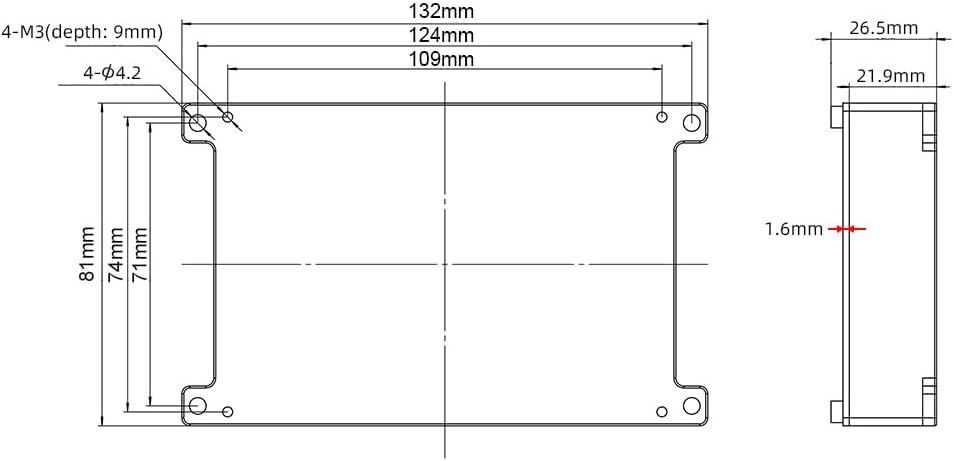
Figure 4.2: Detailed Dimensions of the FT85BD Dual ESC. This technical drawing provides precise measurements for mounting points, overall length, width, and height, including internal clearances.
5. Atụmatụ
The FT85BD Dual ESC incorporates advanced features for enhanced performance and control:
- High-Performance CPU: Utilizes an AT32F403ARCT7 CPU with ARM Cortex-M4 structure, enabling a 240MHz clock speed and a maximum PWM switching frequency of 45KHz for improved motor RPM.
- Versatile Programmability: Fully programmable via the Flipsky ESC Tool, allowing compatibility with various motor types, battery voltages, and control methods.
- Remote Control Integration: Programmable via Flipsky remote controllers VX4 (firmware V1.2.1 or above) and VX3Pro.
- FOC Motor Control: Supports Field-Oriented Control (FOC) for quiet operation and smooth motor startup.
- Real-time Data & Alerts: Provides real-time data monitoring and fault alerts for operational awareness.
- Adaptive PWM Frequency: Features adaptive variable PWM frequency control.
- Multiple Sensor Modes: Supports both sensored (HALL) and sensorless (IPDS, HFPI) motor operation modes.
- Ụdị njikwa: Supports Current and Duty Cycle control types.
- Integrated Smart Switch: Includes slide power-on and automatic shutdown functions, with adjustable auto-shutdown time via the ESC Tool.
- Nkwado Interface: Dedicated fixtures for front lights, rear brake lights, and a horn (12V 3A output).
- Temperature Sensor Support: Compatible with various motor temperature sensors (NTC-10K-100C, PT1000, PTC-1K-100C, KTY, etc.).
6. Ntọlite na Wiring
Careful wiring is essential for the correct and safe operation of the FT85BD Dual ESC. Refer to the diagrams below for proper connections.

Figure 6.1: FT85BD Dual ESC Wiring Diagram Overview. This diagram illustrates the main connections for motors, battery, power switch, and external accessories like lights and horn.

Figure 6.2: Detailed Pinout Diagram for FT85BD Dual ESC Ports. This image provides a close-up view of the various communication and sensor ports, detailing their pin assignments.
6.1. Njikọ ike
- Batrị: Connect your battery pack to the main power wires (red for positive, black for negative) of the ESC. Ensure correct polarity. The ESC supports 4S-20S battery configurations (14-84V).
- Ike mgba ọkụ: Connect the provided self-resetting switch to the designated power switch port (labeled '13. POWER SWITCH' in Figure 6.2). This switch controls the main power to the ESC.
6.2. Motor Connections
- Motor Phase Wires: Connect the three phase wires from each motor to the corresponding outputs on the ESC (typically labeled A, B, C or U, V, W). The FT85BD is a dual ESC, supporting two motors.
- Waya sensọ Hall: If your motors are sensored, connect the Hall sensor wires to the 'HALL' ports (labeled '6. HALL' and '12. HALL' in Figure 6.2). Ensure the correct order of the sensor wires (5V, GND, A, B, C, Temp).
6.3. Communication and Control Connections
- PPM (Pulse Position Modulation): Connect your receiver's PPM output to the 'PPM' port (labeled '1. PPM' or '7. PPM' in Figure 6.2) for throttle control.
- UART (Universal Asynchronous Receiver/Transmitter): Use the 'UART' port (labeled '4. UART' or '10. UART' in Figure 6.2) for connecting compatible FLIPSKY remote controllers (VX4, VX3Pro) or other UART devices for telemetry and control.
- CAN (Controller Area Network): The 'CAN POWER' ports (labeled '3. CAN POWER' or '9. CAN POWER' in Figure 6.2) allow for communication between multiple ESCs or other CAN-enabled devices.
- ADC (Analog-na-Digital Ntụgharị): The 'ADC/PAS' ports (labeled '5. ADC/PAS' or '11. ADC/PAS' in Figure 6.2) can be used for analog throttle input or PAS (Pedal Assist System) sensors.
- USB: Connect the ESC to a computer using the provided USB cable via the 'USB' ports (labeled '2. USB' or '8. USB' in Figure 6.2) for configuration with the Flipsky ESC Tool.
6.4. Ngwa mpụga
- Ọkụ n'ihu: Connect front lights to the designated 'Front Light' port.
- Rear Brake Lights: Connect rear brake lights to the designated 'Brake Light' port.
- mpi: Connect a horn to the designated 'Horn' port.
7. Configuration and Software
The FLIPSKY FT85BD ESC is highly configurable using the Flipsky ESC Tool software.

Figure 7.1: Excerpt from FT85BD Manual V1.4 detailing specifications and features. This image shows a page from the official manual, listing key technical data and functional capabilities.
7.1. Flipsky ESC Tool
The Flipsky ESC Tool is a PC-based software used for configuring parameters, updating firmware, and monitoring the ESC. It is crucial to use the correct version of the software and firmware (V1.4 or above).
- Budata: The software and detailed manual can be downloaded by scanning the QR code provided in Section 10 or by visiting the official Flipsky support page.
- Njikọ: Connect the ESC to your computer via the USB port.
- Femụwe Update: If prompted, update the ESC firmware to the latest compatible version. Ensure the firmware version matches the software version to avoid inconsistencies.
- Ndozi oke: Configure motor parameters (e.g., motor type, pole pairs), battery settings (e.g., voltage limits), control modes, and other advanced settings.
7.2. Remote Controller Configuration
The FT85BD is compatible with FLIPSKY remote controllers like the VX4 and VX3Pro. These remotes can be used to program the ESC (VX4 remote firmware version: VX4_V1.2.1 or above) and provide real-time data.
8. Ọrụ
Once the ESC is properly installed and configured, you can begin operation.
- Ike Na: The ESC supports a slide power-on function. Alternatively, press the connected power switch button.
- Njikwa ọsọ: Utilize your connected remote control (PPM, UART) to control the speed. The ESC supports multiple speed gear levels: Low, Medium, High, and Reverse.
- breeki: The ESC supports regenerative braking, which can return energy to the battery during deceleration.
- Mgbachi akpaaka: The ESC features an automatic shutdown function after a period of inactivity. The shutdown time is adjustable via the Flipsky ESC Tool.
9. Ọrụ nchekwa
The FT85BD ESC includes several protection mechanisms to safeguard the unit and connected components:
- Vol dị alatage Nchedo: Prevents over-discharge of the battery.
- Akwa Voltage Nchedo: Protects against over-voltagntinye.
- Nchekwa gafere ugbu a: Limits current draw to prevent damage to the ESC and motor.
- Temperature Abnormality Protection: Monitors internal temperature and reduces power or shuts down if temperatures exceed safe limits.
- MOSFETs Over-Temperature and Over-Current Protection: Specific protection for the power MOSFETs.
- Nchekwa nfefe batrị: Ensures battery health by preventing excessive discharge.
- Motor Over-Temperature Protection: Protects the motor from overheating when a compatible temperature sensor is connected.
10. Nlekọta
Regular maintenance helps ensure the longevity and reliable performance of your FT85BD Dual ESC.
- Debe Ọcha: Periodically clean the ESC and its connectors to remove dust, dirt, and debris. Use a soft, dry brush or compressed air.
- Nyochaa njikọ: Regularly check all wiring connections for looseness, corrosion, or damage. Secure any loose connections.
- Leba anya na okpomọkụ: During operation, ensure the ESC is not overheating. Adequate airflow is crucial, especially in enclosed spaces.
- Mmelite femụwe: Check the official Flipsky website periodically for firmware updates to benefit from performance improvements and bug fixes.
- Zere mmiri mmiri: While the aluminum case offers some protection, avoid exposing the ESC to excessive moisture or water unless specifically rated for waterproof use.
11. Nchọpụta nsogbu
This section addresses common issues you might encounter with the FT85BD Dual ESC.
- ESC Not Powering On:
- Check battery connection and voltage.
- Ensure the power switch is correctly connected and functioning.
- Nyochaa na agbagoro batrị.
- Motor Not Spinning / Irregular Operation:
- Confirm motor phase wire connections are secure.
- If using sensored motors, check Hall sensor connections.
- Verify motor detection and configuration in the Flipsky ESC Tool.
- Check for fault codes or alerts in the ESC Tool.
- ESC Disconnects from Software:
- Hụ na e jikọrọ eriri USB nke ọma.
- Check for driver issues on your computer.
- Verify that the ESC firmware and software versions are compatible.
- ekpo oke ọkụ:
- Reduce load or operating current.
- Improve airflow around the ESC.
- Check motor and battery parameters in the ESC Tool for appropriate settings.
- Inconsistent Remote Control:
- Recalibrate the remote control in the Flipsky ESC Tool.
- Check remote battery level.
- Ensure the remote's firmware is up to date and compatible.
12. Akwụkwọ ikike
The FLIPSKY FT85BD Dual ESC comes with a warranty period of 2 months (2M+). Please refer to your purchase documentation or contact your retailer for specific warranty terms and conditions.
13. Nkwado
For further assistance, software downloads, and the latest user manual, please refer to the official Flipsky resources.

Figure 13.1: QR Code for Flipsky ESC Tool and User Manual Download. Scan this QR code to access the latest software and documentation.
You can also find the Flipsky ESC Tool and User Manual at the following link:


