1. Okwu mmalite
This manual provides detailed instructions for the installation, operation, and maintenance of the Supermicro MBD-X10SLH-F-O uATX Server Motherboard. Please read this manual thoroughly before beginning installation to ensure proper setup and to maximize the performance and longevity of your system. This motherboard is designed for server applications, supporting Intel LGA1150 processors and DDR3 memory.
2. Ngwaahịa gafereview
The Supermicro MBD-X10SLH-F-O is a high-performance uATX server motherboard featuring the Intel C226 chipset. It is engineered for reliability and efficiency in server environments.
Akụkụ ndị bụ isi:
- Socket CPU: LGA1150, supporting Intel Xeon E3-1200 v3/v4 series, 4th/5th Gen Core i3, Pentium, Celeron processors.
- Ebe nchekwa: 4x 204-pin DDR3-1600 SODIMM slots, supporting up to 32GB ECC/non-ECC Unbuffered memory.
- Oghere Mgbasawanye: 1x PCI-Express 3.0 x16, 1x PCI-Express 2.0 x8, 1x PCI-Express 2.0 x4.
- Nchekwa: 6x SATA3 (6Gbps) ports.
- Njikọta: Dual Gigabit Ethernet LAN ports (2x RJ45) and 1x Dedicated IPMI LAN port (RJ45).
- ọdụ ụgbọ mmiri USB: 4x USB 3.0 ports, 6x USB 2.0 ports.
- Mpụta vidiyo: 1x VGA port.
- Ihe kpatara ụdị: uATX (9.6" x 9.6").
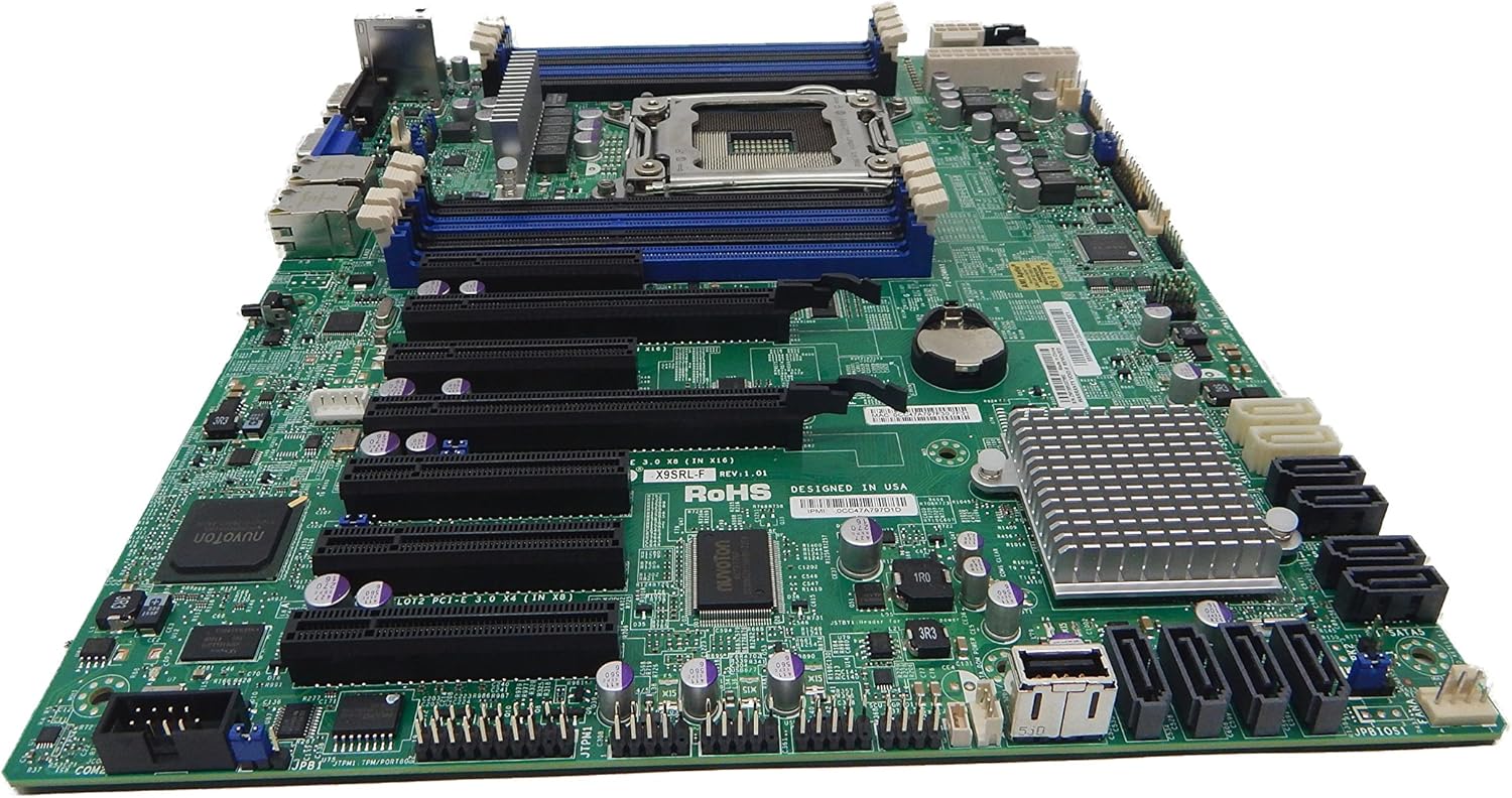
Foto 2.1: Si elu gbadata view of the Supermicro MBD-X10SLH-F-O motherboard, showing the CPU socket, RAM slots, and various expansion slots.

Foto 2.2: N'akuku view of the motherboard, highlighting the LGA1150 CPU socket and the four DDR3 SODIMM memory slots.

Foto 2.3: N'azụ view of the Supermicro MBD-X10SLH-F-O motherboard, displaying the I/O panel with USB, VGA, LAN, and IPMI ports.

Foto 2.4: Agara nso view of the motherboard, showing the six SATA3 ports and other onboard connectors.
3. Nkọwapụta
| Njirimara | Nkọwapụta |
|---|---|
| Ụdị | Supermicro |
| Aha Nlereanya | MBD-X10SLH-F-O |
| Socket CPU | LGA 1150 |
| Ụdị Chipset | Intel C226 |
| Ndị nhazi dakọtara | Intel Core i3-4xxx, i5-4xxx, i7-4xxx, i3-5xxx, i5-5xxx, i7-5xxx, Intel Xeon E3-1200 v3/v4 series |
| Teknụzụ ebe nchekwa RAM | DDR3 |
| Ọsọ ebe nchekwa | 1600 MHz |
| Oke RAM akwadoro | 32 GB |
| Ọnụọgụ nke ọdụ ụgbọ mmiri USB 2.0 | 6 |
| Ọnụọgụ nke ọdụ ụgbọ mmiri USB 3.0 | 4 |
| ọdụ ụgbọ mmiri SATA | 6x SATA3 (6Gbps) |
| Oghere Mgbasawanye | 1x PCIe 3.0 x16, 1x PCIe 2.0 x8, 1x PCIe 2.0 x4 |
| Ụdị Ihe | uATX |
| Akụkụ (LxWxH) | 14 x 11 x 3.5 sentimita asatọ |
| Ibu Ibu | 3.52 ounces |
4. Nhazi
Before beginning installation, ensure your system is powered off and disconnected from the power source. Always handle the motherboard by its edges to avoid static discharge.
4.1. Nwụnye CPU
- Gently lift the CPU socket lever.
- Align the CPU with the socket, ensuring the gold triangle on the CPU matches the triangle on the socket.
- Jiri nlezianya tinye CPU ahụ n'ime oghere ahụ n'amanyeghị ya.
- Lower the socket lever and secure it.
- Tinye mado ọkụ ma wụnye ngwa nju oyi CPU dịka ntuziaka onye nrụpụta ya siri dị.
4.2. Ntinye Ebe Nchekwa
- Mepee obere vidiyo na nsọtụ abụọ nke oghere DIMM.
- Align the memory module's notch with the key in the DIMM slot.
- Pịa ala na nsọtụ abụọ nke modul ebe nchekwa ruo mgbe obere vidiyo ga-adaba n'ebe.
4.3. Ntinye Kaadị Mgbasawanye
- Remove the corresponding slot cover from your chassis.
- Align the expansion card with the desired PCIe slot.
- Press down firmly until the card is fully seated.
- Secure the card with a screw or retention clip.
4.4. Njikọ Ngwaọrụ Nchekwa
- Jikọọ otu nsọtụ nke eriri data SATA na ọdụ ụgbọ mmiri SATA na motherboard.
- Connect the other end of the SATA data cable to your storage device (HDD/SSD).
- Connect a SATA power cable from your power supply to the storage device.
4.5. Njikọ ike
- Jikọọ 24-pin ATX isi ike njikọ site na ike gị na motherboard.
- Connect the 8-pin (or 4-pin) ATX 12V CPU power connector to the motherboard.
4.6. Njikọ ihu panel
Connect the front panel headers (Power LED, HDD LED, Power Switch, Reset Switch, USB, Audio) to the corresponding pins on the motherboard. Refer to the motherboard's silkscreen labels for correct pin orientation.
5. Ntuziaka ọrụ
5.1. Initial Boot-Up
- After all components are installed and connected, connect the power cord to your power supply and turn on the power switch.
- Press the power button on your chassis.
- The system should power on, and you should see a display on your monitor.
5.2. BIOS/UEFI Access
To enter the BIOS/UEFI setup utility, press the designated key (commonly DEL or F2) during the initial boot sequence. The exact key may vary; observe the on-screen prompts.
5.3. IPMI Remote Management
This motherboard features a dedicated IPMI LAN port for remote management. To access the IPMI interface, connect the IPMI LAN port to your network. Obtain the IP address assigned to the IPMI interface (either from BIOS or a network scan) and access it via a web browser from another computer on the same network. Java may be required for remote console functionality.
6. Nlekọta
Regular maintenance helps ensure the stability and longevity of your motherboard and system.
- Mwepụ uzuzu: Na-asachapụ uzuzu site na motherboard na akụrụngwa site na iji ikuku abịakọrọ kwa oge. Gbaa mbọ hụ na agbanyụrụ sistemụ ahụ wee wepụ ya tupu ihicha ya.
- Njikwa USB: Ensure all cables are neatly routed and secured to prevent obstruction of airflow and accidental disconnections.
- Mmelite BIOS/Firmware: Lelee Supermicro website for the latest BIOS and IPMI firmware updates. Follow the provided instructions carefully. Note that IPMI BIOS upgrades may require a separate license. Always update BIOS before IPMI firmware.
- Nyocha akụrụngwa: Occasionally inspect all connections (power, data, expansion cards) to ensure they are securely seated.
7. Nchọpụta nsogbu
Akụkụ a na-ekwu maka nsogbu ndị ị nwere ike izute.
7.1. System Fails to Boot
- Lelee njikọ ike: Ensure the 24-pin ATX and 8-pin CPU power connectors are securely attached.
- Tinyegharịa ihe ndị dị na ya: Remove and re-install the CPU, memory modules, and any expansion cards to ensure they are properly seated.
- Kpochapụ CMOS: Refer to your motherboard's detailed manual for instructions on how to clear the CMOS, which can resolve boot issues caused by incorrect BIOS settings.
- Nhazi kacha nta: Try booting with only essential components (CPU, one RAM stick, power supply, and display) to isolate the problem.
7.2. Fan Speed Issues
Some low RPM, high-efficiency fans may not be accurately detected by the motherboard's fan controller, leading to erratic fan speed behavior (e.g., fans spinning up to max RPM). This is often due to the controller expecting server-grade fans with higher RPM ranges.
- Ntọala BIOS: Check BIOS settings for fan control options. Adjust fan curves or modes if available.
- 3-Pin vs. 4-Pin Fans: If using 4-pin PWM fans that exhibit this behavior, consider using 3-pin adapters if available with your fans. This can sometimes provide a more stable, albeit less precise, fan control.
- IPMI Fan Control: While IPMI offers fan control, it may have limitations for low RPM fans.
7.3. SATA Port Obstruction
When installing a full-size graphics processing unit (GPU), some SATA ports may become physically blocked or difficult to access.
- Atụmatụ n'ihu: Connect SATA cables to the necessary ports before installing large expansion cards.
- Angled SATA Cables: Use SATA cables with angled connectors if straight connectors are obstructed.
- Alternative Ports: Utilize any unblocked SATA ports first.
8. Akwụkwọ ikike na Ozi Nkwado
For detailed warranty information, including terms, conditions, and duration, please refer to the official Supermicro website or the warranty card included with your product. For technical support, driver downloads, and additional documentation, visit the Supermicro support portal.
Supermicro Official Websaịtị: www.mmagene.co.uk


