1988 Ford Truck (CAB) Wiring Diagram Manual
Models Covered: F600, F700, F800, FT800, FT900
1. Okwu mmalite
This manual provides essential information for understanding and utilizing the original foldout wiring diagram for 1988 Ford F-Series and FT-Series trucks. This diagram is a critical resource for electrical system diagnosis, repair, and maintenance for the specified models.
The diagram details the complete electrical system, including circuits for the engine, chassis, lighting, instrumentation, and accessories. Familiarity with its layout and symbols is crucial for accurate interpretation.
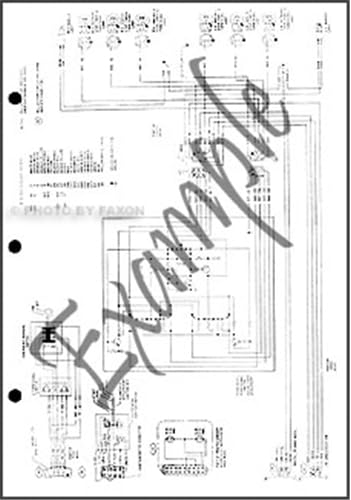
Image 1.1: Front cover of the 1988 Ford Truck Wiring Diagram. This image displays the manual's cover, indicating its title and year, which helps in identifying the correct diagram.
2. Understanding the Wiring Diagram
The wiring diagram uses standardized symbols and color codes to represent electrical components and circuits. Understanding these conventions is fundamental to correctly interpreting the information presented.
2.1. Symbols and Abbreviations
Refer to the legend typically located on the diagram itself for a comprehensive list of symbols and their meanings. Common symbols include:
- Ahịrị: Represent wires. Different line styles may indicate specific wire types or functions (e.g., shielded, twisted pair).
- Rectangles/Circles: Often represent components like relays, switches, motors, or lights.
- Dashed Lines: May indicate internal connections within a component or optional circuits.
- Ground Symbol: Indicates a connection to the vehicle's chassis ground.
- Njikọ: Depicted to show where wires connect or disconnect, often with pin numbers.
2.2. Wire Color Codes
Wires are typically color-coded to aid in identification. The diagram's legend will specify the full and abbreviated color codes (e.g., R for Red, BK for Black, LG for Light Green). Some wires may have a primary color and a stripe color (e.g., R/W for Red with White stripe).
2.3. Circuit Flow
Circuits generally flow from the power source (battery/alternator) through fuses, switches, components, and then to ground. Follow the lines and symbols to trace the path of electricity for a specific function.
3. Nchekwa nchekwa
WARNING: Working with automotive electrical systems can be dangerous and may result in serious injury or damage to the vehicle if proper precautions are not followed.
- Always disconnect the vehicle's battery negative terminal before performing any electrical work to prevent accidental short circuits or component damage.
- Use appropriate personal protective equipment, including safety glasses and insulated gloves.
- Never probe wires with sharp objects that could pierce insulation and cause a short.
- Ensure all connections are secure and properly insulated after completing repairs.
- Consult a certified automotive technician if you are unsure about any procedure.
4. Using the Diagram for Diagnosis and Repair
The wiring diagram is an invaluable tool for diagnosing electrical issues and performing repairs.
4.1. Troubleshooting Electrical Problems
- Chọpụta sekit emetụtara: Locate the specific circuit on the diagram related to the malfunction (e.g., headlights, turn signals, engine sensors).
- Trace Power Flow: Follow the circuit from the power source, through fuses, switches, and components, to ground.
- Check for Continuity and Voltage: Jiri multimeter nwalee maka voltage at various points and continuity across wires and components. Compare readings to expected values.
- Nyochaa njikọ: Pay close attention to connectors, splices, and ground points, as these are common failure areas.
4.2. Component Identification and Location
The diagram often includes references to component locations within the vehicle, or it may be used in conjunction with a service manual that provides detailed component location diagrams. Use the diagram to identify the correct wires leading to and from specific components.
4.3. Repair and Modification
When replacing components or making modifications, always refer to the diagram to ensure correct wiring and to avoid creating new electrical problems. Use appropriate gauge wires and connectors that match or exceed original specifications.
5. Nlekọta na Nchekwa
To ensure the longevity and readability of your foldout wiring diagram:
- Store the diagram flat or gently folded in a clean, dry environment, away from direct sunlight and extreme temperatures.
- Zere créasing or tearing the folds, as this can obscure critical information.
- Keep the diagram free from grease, oil, and other contaminants that can degrade the paper and ink.
- Handle with clean hands to prevent smudges.
6. Nkọwapụta
| Njirimara | Nkọwa |
|---|---|
| Afọ mbipụta | 1988 |
| Onye mbipụta | Ford |
| Asụsụ | Bekee |
| Ogologo Bipụta | 7 pages (Foldout) |
| Akụkụ | 17 x 11 x 0.25 sentimita (apịaji) |
| Ibu Ibu | 13.4 ounces |
| Usoro | Foldout Wiring Diagram |
7. Nkwado na Akụrụngwa Ndị Ọzọ
For further assistance with your 1988 Ford Truck electrical system, consider the following:
- Consult a certified automotive technician specializing in vintage Ford trucks.
- Refer to a complete 1988 Ford Truck service manual for detailed repair procedures and component locations.
- Online automotive forums and communities dedicated to classic Ford trucks can be a valuable source of information and peer support.
As this is an original publication from 1988, direct manufacturer support or warranty information is no longer applicable.


