1. Okwu mmalite
The Velleman DVM810 is a compact and economical 3 1/2 digit digital multimeter designed for measuring DC and AC voltages, DC currents, resistance, and for performing diode and transistor (hFE) tests. It features overload protection and automatic polarity indication, making it suitable for hobbyists, field use, and workshops. This manual provides essential information for the safe and effective operation of your DVM810 multimeter.
2. Akụrụngwa Ngwaahịa
- Automatic polarity indication
- Voltage measurements: AC 500V and DC 500V maximum
- Current measurements: DC 10A maximum (0.2A fused, 10A unfused)
- Resistance measurements: Up to 2MΩ
- Diode and transistor (hFE) test functions
- Nchekwa oke ibu
- Compact design with 3 1/2 digit LCD display
3. Ihe ngwugwu
Biko lelee ọdịnaya nke ngwugwu ahụ ka ị hụ na ihe niile dị:
- Velleman DVM810 Digital Multimeter
- Nduzi Ule (otu uhie, otu oji)
- Akwụkwọ ntuziaka
4. Ozi nchekwa dị mkpa
Read all safety warnings and instructions carefully before using this product. Failure to follow these instructions may result in electric shock, fire, or serious injury.
- Always ensure the multimeter is set to the correct function and range before making any measurements.
- Never exceed the maximum input limits for any range. The maximum voltage for AC/DC is 500V.
- Do not attempt to measure current on circuits with voltagihe karịrị 250 V.
- Inspect test leads for damaged insulation or exposed metal before each use. Replace damaged leads immediately.
- Ejila multimeter ahụ ma ọ bụrụ na o yiri ka ọ mebiri emebi ma ọ bụ ọ bụrụ na akpa ahụ emepeela.
- Exercise extreme caution when working with live circuits. Use appropriate personal protective equipment.
- Always disconnect power to the circuit and discharge high-voltage capacitors before measuring resistance or performing diode/transistor tests.
- Replace the battery when the low battery indicator appears on the display to ensure accurate readings.
5. Ngwaahịa gafereview
Familiarize yourself with the components of your Velleman DVM810 multimeter:
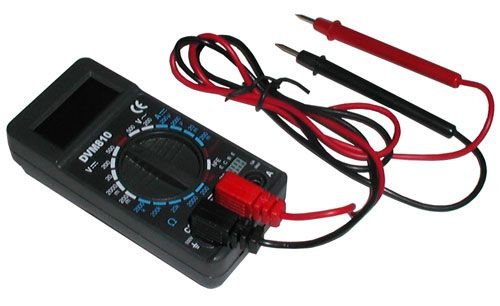
Figure 1: Velleman DVM810 Digital Multimeter. This image displays the front view of the compact multimeter, highlighting its liquid crystal display (LCD), the central rotary function switch, and the input jacks for test leads at the bottom.
- Ngosipụta LCD: Shows measurement readings, units, and polarity.
- Ngbanwe Rotary: Used to select the desired measurement function and range.
- Ntinye Jacks:
- COM Jack: Common (negative) input for all measurements. Connect the black test lead here.
- VΩmA Jack: Ntinye dị mma maka voltage, resistance, and current measurements up to 200mA. Connect the red test lead here.
- 10A Jack: Positive input for high current measurements (up to 10A). Connect the red test lead here for 10A measurements.
- Nleba ule: Red and black leads used to connect the multimeter to the circuit under test.
6. Nhazi
6.1 Ntinye batrị
The DVM810 multimeter requires a 9V battery (not always included). To install or replace the battery:
- Ensure the multimeter is turned OFF (rotary switch set to OFF).
- Chọta ebe mkpuchi batrị n'azụ unit ahụ.
- Remove the screw(s) securing the cover and carefully lift it off.
- Connect a new 9V battery to the battery clip, observing correct polarity.
- Tinye batrị ahụ n'ime ebe nchekwa ahụ wee dochie mkpuchi ahụ, jiri skru(s) jide ya.
6.2 Njikọ Ndị Nnwale Nlele
Always connect the test leads correctly for accurate and safe measurements:
- Tinye ụzọ ule ojii n'ime COM (common) jack.
- Maka ọtụtụ nha (mkpụrụ)tage, resistance, diode, hFE, and current up to 200mA), insert the red test lead into the VmA jakị.
- For high current measurements (up to 10A), insert the red test lead into the 10A jakị.
7. Ntuziaka ọrụ
Before making any measurement, ensure the test leads are correctly connected and the rotary switch is set to the appropriate function and range.
7.1 Na-atụ DC Voltage (V=)
- Fanye ndu uhie n'ime VmA jack and the black lead into the COM jakị.
- Tọọ mgba ọkụ rotary na DC Vol achọrọtage (V=) range. Start with the highest range if the voltage amaghi.
- Connect the test leads across the component or circuit to be measured (in parallel).
- Gụọ voltage value on the LCD display. The display will show the correct polarity.
7.2 Na-atụ AC Voltage (V~)
- Fanye ndu uhie n'ime VmA jack and the black lead into the COM jakị.
- Tọọ mgba ọkụ na-agbanwe agbanwe na AC Vol achọrọtage (V~) range. Start with the highest range if the voltage amaghi.
- Connect the test leads across the component or circuit to be measured (in parallel).
- Gụọ voltage uru na LCD ngosi.
7.3 Measuring DC Current (A=)
Caution: Never connect the multimeter in parallel with a voltagisi iyi mgbe ị na-atụ ọkụ eletrik, n'ihi na nke a nwere ike ịfụ fuse ma ọ bụ mebie mita ahụ.
- Determine the expected current. For currents up to 200mA, insert the red lead into the VmA jack. For currents up to 10A, insert the red lead into the 10A jack. Always insert the black lead into the COM jakị.
- Set the rotary switch to the appropriate DC Current (A=) range. Start with the highest range if the current is unknown.
- Turn off power to the circuit. Open the circuit where the current is to be measured.
- Connect the multimeter in series with the circuit.
- Restore power to the circuit and read the current value on the LCD display.
7.4 Measuring Resistance (Ω)
Caution: Ensure the circuit is completely de-energized and all capacitors are discharged before measuring resistance.
- Fanye ndu uhie n'ime VmA jack and the black lead into the COM jakị.
- Set the rotary switch to the desired Resistance (Ω) range. Start with a higher range if the resistance is unknown.
- Jikọọ ihe nlele ndị a ga-eji tụọ.
- Gụọ uru iguzogide na ngosipụta LCD.
7.5 Diode Ule
Caution: Ensure the diode is disconnected from the circuit or the circuit is de-energized before testing.
- Fanye ndu uhie n'ime VmA jack and the black lead into the COM jakị.
- Set the rotary switch to the Diode symbol (→|).
- Connect the red lead to the anode and the black lead to the cathode of the diode. The display will show the forward voltage drop (typically 0.5V to 0.8V for silicon diodes).
- Reverse the leads. The display should show 'OL' (Overload) for a good diode. If it shows a reading in both directions or 'OL' in both directions, the diode may be faulty.
7.6 Transistor (hFE) Test
Caution: Ensure the transistor is disconnected from the circuit before testing.
- Fanye ndu uhie n'ime VmA jack and the black lead into the COM jakị.
- Tọọ ngbanwe rotary na ọnọdụ hFE.
- Identify if the transistor is NPN or PNP. Insert the transistor's emitter, base, and collector leads into the corresponding holes in the hFE socket on the multimeter.
- Gụọ uru hFE (DC current gain) na ihuenyo LCD.
8. Nkọwapụta
| Oke | Uru |
|---|---|
| Ụdị | Velleman |
| Nọmba nlereanya | DVM810 |
| Ụdị nha | Multimeter |
| DC Voltage Oke | Ruo 500V |
| AC Voltage Oke | Ruo 500V |
| DC dị ugbu a | Up to 10A (0.2A fused, 10A unfused) |
| Oke mgbochi | Up to 2MΩ |
| Nnwale Diode | Ee |
| Ule Transistor (hFE) | Ee |
| Ngosipụta | 3 1/2 Digit LCD |
| Isi Iyi Ike | Batrị 9V (anaghị etinye ya) |
| Akụkụ | Ihe dị ka 3.70" x 1.81" x 1.03" |
| Ibu Ibu | Approximately 3.2 ounces (0.2 lbs) |
| UPC | 836479002272 |
9. Nlekọta
9.1 nnọchi batrị
When the low battery indicator appears on the LCD, replace the 9V battery as described in Section 6.1. A weak battery can lead to inaccurate readings.
9.2 Nhicha
Iji hichaa multimeter, hichaa akpa ahụ na mgbasa oziamp cloth and a mild detergent. Do not use abrasives or solvents. Ensure the unit is completely dry before use.
9.3 Test Lead Inspection
Regularly inspect the test leads for any signs of damage, such as cracked insulation, exposed wires, or loose connections. Replace damaged leads immediately to prevent electric shock hazards.
10. Nchọpụta nsogbu
- Enweghị ngosipụta ma ọ bụ ngosipụta dị nro: Lelee batrị ahụ. Dochie ya ma ọ bụrụ na ọ dị mkpa.
- Ọgụgụ na-ezighi ezi:
- Hụ na agbanwere ihe mgba ọkụ ahụ ka ọ dabara na ọrụ na oke kwesịrị ekwesị.
- Lelee batrị voltage; replace if low.
- Gbaa mbọ hụ na ejikọtara ụzọ nnwale nke ọma ma ghara imebi.
- For resistance measurements, ensure the circuit is de-energized.
- 'OL' (Overload) egosiri: The measured value exceeds the selected range. Select a higher range or ensure the circuit is within the meter's capabilities.
- Fuse blown (during current measurement): If the meter stops measuring current, the internal fuse may have blown. Refer to a qualified technician for fuse replacement.
11. Akwụkwọ ikike na nkwado
Warranty information for the Velleman DVM810 Digital Multimeter is typically provided with your purchase documentation or can be found on the official Velleman website. For technical support, service, or further inquiries, please refer to the contact information provided by your retailer or the manufacturer's official support channels.


