
1. Okwu mmalite
This manual provides detailed instructions for the installation, operation, and management of your MokerLink 8-Port 10G Managed Ethernet Switch. This device is designed to enhance network performance and efficiency with its high-speed connectivity and advanced management features. Please read this manual thoroughly before using the product to ensure proper setup and functionality.
2. Ngwaahịa gafereview
The MokerLink 8-Port 10G Managed Ethernet Switch features a robust design for high-bandwidth network environments. It includes 4x10Gbps Ethernet RJ45 ports and 4x10Gbps SFP+ slots, offering versatile connectivity options for various network devices. The switch supports a 160Gbps switching capacity and a packet forwarding rate of 119.04Mpps, ensuring non-blocking 10G line speed forwarding across all ports.
Atụmatụ gụnyere:
- Ọdụ ụgbọ mmiri dị elu: 4x10Gbps RJ45 ports (auto-adaptive 10G/5G/2.5G/1000M/100M) and 4x10Gbps SFP+ slots (compatible with 1G/10G optical modules).
- Bandwit dị elu: 160Gbps switching capacity and 119.04Mpps packet forwarding rate.
- L3 Management: Na-akwado Web and Command Line Interface (CLI) for comprehensive device and port configuration, including IPv4/IPv6 management and routing.
- Advanced Layer 2 Features: VLAN, ACL, QoS, Jumbo frame, DHCP, security, multicast, MAC address table, diagnosis, Statistics, MSTP/RSTP/STP.
- Security & Diagnosis: AAA/802.1X/MAC-Based authentication, DoS anti-attack, dynamic ARP inspection, DHCP Snooping, IP Source Guard, Port Security, Protected Ports, storm control, Console/RAM/Flash Logs, Port Mirroring, Ping, Traceroute, Port Tests, UDLD Protocol.
- Nhazi na-adịgide adịgide: Metal case with industrial-grade fan for efficient heat dissipation, suitable for desktop or wall-mounting.
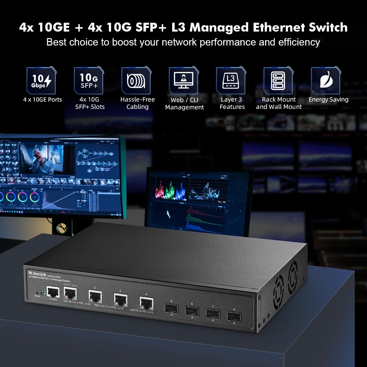
Figure 2.1: MokerLink 8-Port 10G Managed Ethernet Switch highlighting key features like 10G ports, SFP+ slots, Web/CLI management, L3 features, rack/wall mount, and energy saving.

Figure 2.2: Front and rear panel view of the switch, showing 4x10Gbps RJ45 ports, 4x10Gbps SFP+ slots, console port, reset button, power indicator, system indicator, and external power supply input.
3. Ihe ngwugwu
Verify the contents of your package upon opening. If any items are missing or damaged, please contact your vendor.
- 1 x MokerLink 10G Managed Switch
- 1 x nkwụnye ọkụ
- Akwụkwọ ntuziaka onye ọrụ 1 x (akwụkwọ a)
- Mounting Accessories (for desktop or wall-mount installation)
4. Nhazi
4.1 Nwụnye anụ ahụ
The MokerLink 8-Port 10G Managed Ethernet Switch is designed for flexible deployment, supporting both desktop and wall-mount installations.
- Ndokwa Desktọpụ: Place the switch on a flat, stable surface, ensuring adequate ventilation around the device.
- Mgbakwasị mgbidi: Use the provided mounting accessories to securely attach the switch to a wall. Ensure the mounting location is sturdy and allows for proper cable management and ventilation.
4.2 Ijikọ ngwaọrụ netwọkụ
Connect your network devices (e.g., servers, workstations, NAS, WiFi 6/7 APs) to the switch's RJ45 or SFP+ ports.
- ọdụ ụgbọ mmiri RJ45: Use appropriate Ethernet cables for optimal performance. For 10Gbps connections, Cat6a or Cat7 cables are recommended. For 2.5Gbps/5Gbps, Cat5e or Cat6 cables are suitable.
- SFP+ Slots: Insert compatible 1G or 10G SFP/SFP+ optical modules into the slots, then connect fiber optic cables to the modules.

Figure 4.1: The switch connected to various high-performance devices such as WiFi 6/7 AP, servers, workstations, NAS, and 4K/8K video systems, illustrating cable type recommendations for different speeds.
4.3 Na-agbanye ike
Connect the provided power adapter to the switch's power input and then to a power outlet. The Power LED (P) on the front panel should illuminate, indicating the switch is receiving power. The System LED (S) will blink during startup and remain steady when the system is operational.
5. Ntuziaka ọrụ
5.1 LED egosi
Igwe ọkụ ihu ihu na-enye ozi ọkwa:
- P (Power Indicator):
- Gbanye: A na-enye ike.
- Gbanyụọ: Enweghị ike.
- S (System Indicator):
- On: The system is normal.
- Off: System startup or abnormality.
- RJ45 Port LEDs (Left/Right):
- Left LED (Link/Activity): Orange for 10Gbps, Green for 5Gbps, 2.5Gbps, 1Gbps, or 100Mbps. Blinks for activity.
- Right LED (Speed): Orange for 10Gbps, Green for 1Gbps.
- Igwe ọkụ ọdụ ụgbọ mmiri SFP:
- Led: Orange for 10Gbps, Green for 1Gbps. Blinks for activity.
5.2 Initial Access to Management Interface
The switch can be managed via a Web-based interface or Command Line Interface (CLI).
- Web Ihuenyo: Access the switch by entering its default IP address (typically 192.168.2.1) into a web browser. The default username is 'admin' and the default password is 'admin'.
- CLI: Connect to the console port using a console cable and a terminal emulator, or use Telnet/SSH for remote access.

Figure 5.1: Illustration of accessing the switch's management interfaces, including the web interface and command line interface, with default login credentials.
6. Management Features
The MokerLink 8-Port 10G Managed Ethernet Switch offers a comprehensive suite of Layer 2 and Layer 3 management features.
6.1 Layer 2 Switching Features
- VLAN ( Netwọk Mpaghara Virtual): Supports 802.1Q Tag-based VLANs to segment networks and improve security and performance.
- Link Aggregation (LACP): Combines multiple physical links into a single logical link to increase bandwidth and provide link redundancy.
- QoS (Oru ọrụ): Prioritizes network traffic to ensure critical applications receive sufficient bandwidth and low latency.
- MSTP/RSTP/STP: Spanning Tree Protocols prevent network loops.
- Frames Jumbo: Supports larger Ethernet frames for increased data throughput.

Ọgụgụ 6.1: Ọpụample of 802.1Q Tag-based VLANs segregating network traffic for different devices like cameras, servers, and IP phones.

Figure 6.2: Illustration of Link Aggregation (LACP) connecting the switch to another switch and a NAS for enhanced bandwidth and resilience.

Figure 6.3: QoS mechanism prioritizing audio, video, and data traffic to reduce packet loss and latency.
6.2 Layer 3 Routing Features
- IPv4/IPv6 Management: Supports both IPv4 and IPv6 protocols for network addressing and routing.
- Ụzọ kwụ ọtọ: Configurable static routes for directing traffic between different IP networks.
- ARP (Protocol mkpebi mkpebi adreesị): Manages the mapping of IP addresses to MAC addresses.
- Loopback Interface: A virtual interface used for management and routing protocols.
6.3 Security and Diagnosis
- AAA/802.1X/MAC-Based Authentication: Provides robust user and device authentication.
- DoS Anti-Attack: Na-echebe megide mbuso agha agọnarị ọrụ.
- DHCP Snooping & IP Source Guard: Prevents unauthorized DHCP servers and IP spoofing.
- Nchekwa ọdụ ụgbọ mmiri: Limits the number of MAC addresses on a port to prevent unauthorized access.
- Njikwa oke ifufe: Prevents network performance degradation due to excessive broadcast, multicast, or unknown unicast traffic.
- N'iji Port: Duplicates network traffic from one port to another for monitoring and analysis.
- Ping, Traceroute, Port Tests: Diagnostic tools for network connectivity and performance.
- UDLD Protocol: Unidirectional Link Detection protocol to detect and disable unidirectional links.
- Nchọpụta loop: Identifies and removes network loops to prevent traffic disruptions.

Figure 6.4: Loop detection feature identifying and preventing network loops between two switches, ensuring stable network operation.
7. Nlekọta
Regular maintenance ensures the longevity and optimal performance of your switch.
- Femụwe ọjọọ: Periodically check the MokerLink official website for firmware updates to enhance features and improve security. Follow the provided instructions for a safe upgrade process.
- Configuration Backup/Restore: Regularly back up your switch configuration to prevent data loss. This allows for quick restoration in case of misconfiguration or device replacement.
- Ọnọdụ gburugburu: Ensure the switch operates within recommended temperature and humidity ranges. Maintain clear airflow around the device to facilitate heat dissipation by the industrial-grade fan.
- Nhicha: Keep the switch clean and free from dust. Use a soft, dry cloth for cleaning.
8. Nchọpụta nsogbu
Akụkụ a na-ekwu maka nsogbu ndị ị nwere ike izute.
8.1 Enweghị ike
- Gbaa mbọ hụ na ejikọrọ ihe nkwụnye ọkụ ahụ na mgba ọkụ yana ebe ọkụ na-arụ ọrụ.
- Nyochaa na ntinye ọkụ na-arụ ọrụ site na nkwụnye na ngwaọrụ ọzọ.
- Lelee ihe nkwụnye ọkụ maka mmebi ọ bụla a na-ahụ anya.
8.2 Enweghị njikọ na ọdụ ụgbọ mmiri
- Check the Ethernet or fiber cable connection at both ends. Ensure cables are not damaged.
- Nyochaa na agbanyere ngwaọrụ ejikọrọ ma na-arụ ọrụ nke ọma.
- Ensure the correct cable type is used for the speed (e.g., Cat6a/7 for 10G RJ45).
- Lelee ọkwa ọdụ ụgbọ mmiri na interface njikwa mgba ọkụ.
- Try connecting to a different port on the switch or using a different cable.
8.3 Enweghị ike ịnweta Web Interface
- Ensure your computer's IP address is in the same subnet as the switch's default IP (192.168.2.x, with subnet mask 255.255.255.0).
- Verify the switch's IP address has not been changed from the default (192.168.2.1).
- Hichapụ cache ihe nchọgharị gị ma ọ bụ nwaa ihe nchọgharị dị iche.
- Gbanyụọ firewall ma ọ bụ ngwa nje ọ bụla na kọmputa gị nwa oge.
8.4 Ịtọgharịa na Ntọala ụlọ ọrụ
If you forget the password or encounter persistent issues, you can restore the switch to its factory default settings.
- With the switch powered on, locate the Tọgharia bọtịnụ na ogwe ihu.
- Use a paperclip or a similar pointed object to press and hold the Reset button for approximately 6 seconds.
- Release the button. The switch will reboot with factory default settings.
9. Nkọwapụta
| Njirimara | Nkọwa |
|---|---|
| Ụdị | MokerLink |
| Nọmba nlereanya | 4x10G + 4x10G SFP Managed |
| Ọnụọgụ nke ọdụ ụgbọ mmiri | 9 (4x10Gbps RJ45, 4x10Gbps SFP+, 1xConsole) |
| Ngwa gụnyere | 10G Managed Switch |
| Agba | Nwa |
| Ngwa dakọtara | Desktọpụ |
| Interface | RJ45, SFP+ |
| Ọnụego mbufe data | 160 Gigabits kwa nkeji (Ike mgbanwe) |
| Ngbanwe Ụdị | Managed (L3) |
| MAC Okwu Isiokwu Size | 16K |
| Ọnụego mbugharị ngwugwu | 119.04 Mpps |
| Nlekọta | Web, CLI, Telnet, SSH, SNMP |
| Oriri ike | Empty Load Power: <36W |
10. Akwụkwọ ikike na nkwado
10.1 Ozi akwụkwọ ikike
The MokerLink 8-Port 10G Managed Ethernet Switch comes with a Akwụkwọ ikike nke afọ 1 site na ụbọchị ịzụrụ. Akwụkwọ ikike a na-ekpuchi ntụpọ dị na ngwa na arụ ọrụ n'okpuru ojiji nkịtị. Ọ naghị ekpuchi mmebi nke n'ụzọ na-ezighị ezi, ihe mberede, mgbanwe na-akwadoghị, ma ọ bụ ihe na-akpata mpụga.
10.2 Nkwado nka na ụzụ
For technical assistance, troubleshooting, or warranty claims, please contact MokerLink customer support through the official website or your point of purchase. Please have your product model number and purchase information ready when contacting support.