
1. Okwu mmalite
The MokerLink 8 Port 10 Gigabit PoE Web Managed Switch is designed to provide high-speed network connectivity and Power over Ethernet (PoE) capabilities for various applications. This managed switch features 7x 10Gbps Ethernet ports with PoE++ support and 1x 10Gbps SFP+ port for fiber optic uplinks, offering a total switching capacity of 160Gbps.
Atụmatụ gụnyere:
- 10G ọdụ ụgbọ mmiri: 7x 10Gbps Ethernet ports supporting 10G/5G/2.5G/1000M/100M auto-negotiation, and 1x 10Gbps SFP+ port for 1G/10G optical fiber modules.
- Nkwado PoE++: Ports 1-7 support IEEE 802.3af/at/bt PoE, with each port providing up to 90W and a total power budget of 260W.
- Web Njikwa: Offers L2 management features such as QoS, ACL, Link Aggregation (LACP), VLAN configuration, Port Mirroring, Storm Control, and SNMP.
- Bandwit dị elu: 160Gbps switching capacity ensures non-blocking 10G line speed forwarding across all ports.
- Nhazi na-adịgide adịgide: Features a metal case and smart fan for efficient heat dissipation and stable operation.

gafereview of the MokerLink 8 Port 10 Gigabit PoE Web Managed Switch highlighting its key features.
2. Ihe ngwugwu
Chọpụta na ngwungwu gị nwere ihe ndị a:
- 1x MokerLink 10G Managed PoE Switch
- 1 x eriri ọkụ
- 1x Mount kit
3. Nkọwa anụ ahụ
Nhazi Ogwe ihu
The front panel of the switch features all network ports, LED indicators, and a reset button.
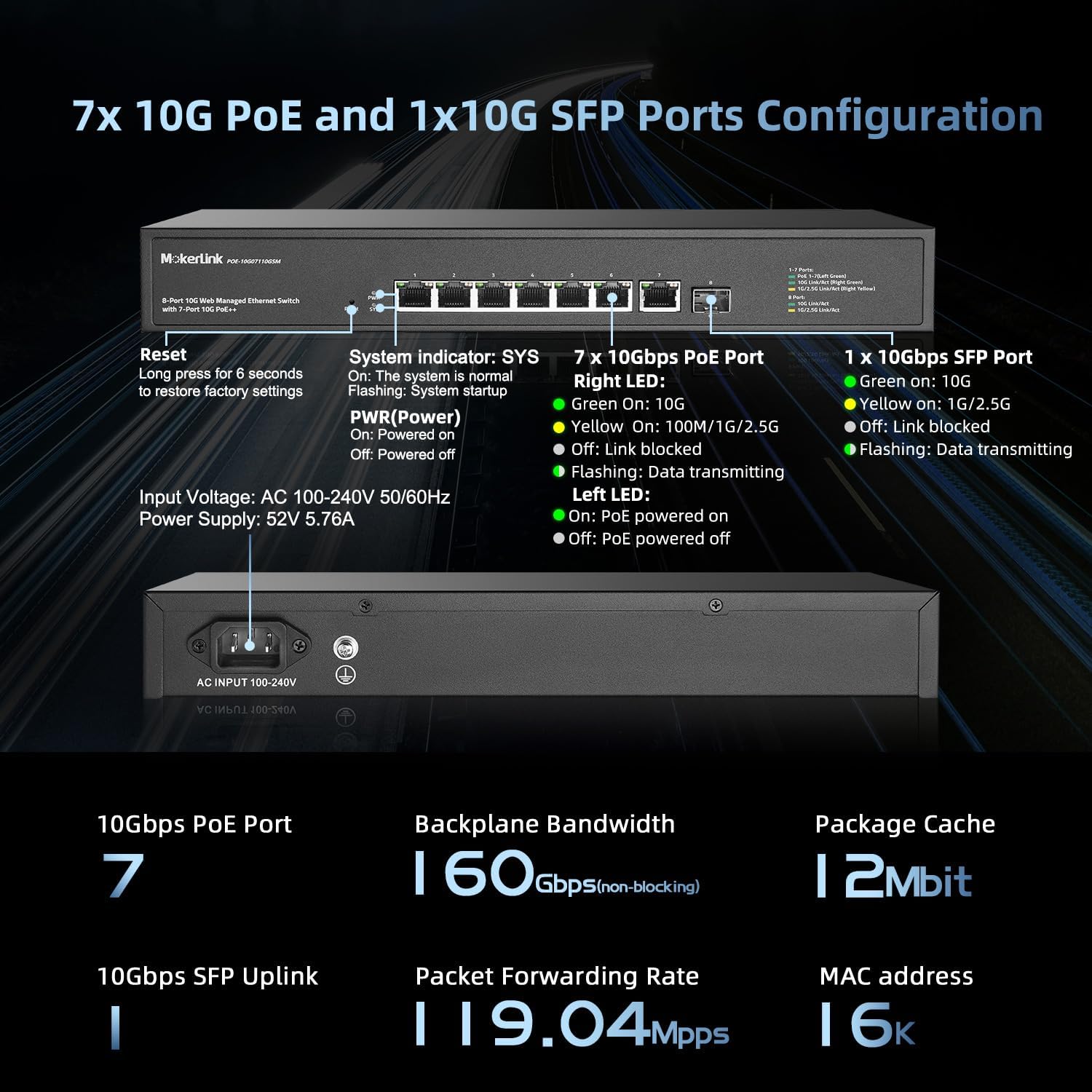
Zuru ezu view of the switch's front panel with ports, LEDs, and reset button.
- Ọdụ ụgbọ mmiri 1-7: 10Gbps Ethernet ports with PoE++ support.
- Ijebu 8: 10Gbps SFP+ port for fiber optic connections.
- Tọgharịa bọtịnụ: Pịa ma jide sekọnd 6 iji weghachi ntọala ụlọ ọrụ.
- SYS (System Indicator) LED: Green when the system is normal, flashing during system startup.
- PWR (Ike) LED: On when powered on, off when powered off.
- Port LEDs (Right LED): Green for 10G link, Yellow for 100M/1G/2.5G link. Flashing indicates data transmitting. Off indicates link blocked.
- Port LEDs (Left LED): On when PoE is powered on, off when PoE is powered off.
4. Nhazi
4.1 Njikọ ike
Connect the provided power cable to the AC input on the rear panel of the switch and then to a standard AC power outlet (100-240V, 50/60Hz).
4.2 Njikọ netwọkụ
- Ngwaọrụ Ethernet: Connect your network devices (e.g., computers, routers, NVRs) to ports 1-7 using appropriate Ethernet cables (CAT5e, CAT6, CAT6a/7).
- Ngwa PoE: For Power over Ethernet devices (e.g., IP cameras, wireless access points, IP phones), connect them to ports 1-7. The switch will automatically detect and provide power to compliant IEEE 802.3af/at/bt devices.
- SFP+ Uplink: Insert a compatible 1G/10G SFP+ optical fiber module into port 8 for fiber optic connections to other network devices or a core switch.

Connecting PoE and non-PoE devices to the switch.
4.3 Nke mbụ Web Nweta njikwa
To access the switch's web njikwa interface maka nhazi:
- Connect a computer directly to any Ethernet port (1-7) of the switch.
- Configure your computer's IP address to be in the same subnet as the switch's default IP address. For example, if the switch's default IP is 192.168.2.1, set your computer's IP to 192.168.2.100 with a subnet mask of 255.255.255.0.
- Mepee a web browser (e.g., Chrome, Firefox) and enter the default IP address of the switch: http://192.168.2.1
- When prompted, enter the default username: admin and default password: admin.
- You will then access the web management interface to configure the switch.

Ịnweta na web management interface with default IP and credentials.
5. Ntuziaka ọrụ
5.1 Web Njikwa Njikwa
Nke web management interface provides comprehensive control over the switch's functions. After logging in, you can configure various Layer 2 features to optimize your network.

gafereview of Lite L2 Management Features.
- VLAN ( Netwọk Mpaghara Virtual): Configure 802.1Q Tag-based VLANs to segment your network, creating virtual boundaries for improved security and traffic management without additional hardware.

802.1Q Tag-based VLAN configuration example.
- QoS (Oru ọrụ): Prioritize network traffic to ensure critical applications like audio and video receive sufficient bandwidth, reducing packet loss and latency.

QoS (Quality of Service) prioritization.
- Link Aggregation (LACP): Increase bandwidth and improve network resilience by grouping multiple physical Ethernet links into a single logical channel.

Link Aggregation (LACP) for increased bandwidth.
- Nchọpụta loop: Automatically detect and prevent network loops, which can cause broadcast storms and network instability, ensuring smooth network operation.

Loop Detection to prevent network issues.
- Atụmatụ ndị ọzọ: Nke web interface also allows configuration of ACLs, Storm Control, Spanning Tree Protocol (STP/RSTP), Port Mirroring, Port Isolation, Port Rate-limit, Port Security, and SNMP for comprehensive network management.
5.2 PoE Port Configuration
N'ime web management interface, you can monitor the real-time power supply status of each PoE port (1-7) and configure individual PoE settings as needed. This includes enabling or disabling PoE for specific ports and viewing power consumption.
5.3 SFP+ Port Usage
The 10Gbps SFP+ port (Port 8) supports standard SFP optical modules (1G/10G) without encryption. This allows for flexible fiber optic connections using multi-mode, single-mode, or SFP to RJ45 modules (modules not included by default).
6. Nlekọta
6.1 Nhazi nhazi
After making any changes to the switch's settings via the web management interface, it is crucial to navigate to the "Save" option within the menu and confirm to permanently apply the configuration. Changes not explicitly saved will revert to the previous state or default settings upon a device reboot or power cycle.
6.2 Mgbasa ọkụ
The switch is equipped with a smart fan system designed for efficient heat dissipation, ensuring stable and reliable operation. To maintain optimal performance, ensure that the switch is placed in a location with adequate airflow and that its ventilation openings are not obstructed.
7. Nchọpụta nsogbu
- Switch Unreachable After IP Change: If the switch becomes inaccessible after modifying its IP address, ensure your computer's IP address is configured within the same subnet as the new switch IP. You may also need to clear the ARP cache on your computer. If the configuration was not saved, power cycling the switch will revert it to the default IP address (192.168.2.1).
- Njikọ Ike anaghị akwụsi ike: Ensure the power cable is firmly connected to both the switch's AC input and the power outlet. A loose connection can lead to unexpected reboots or intermittent operation.
- VLAN Configuration Issues: If VLANs are not functioning as expected, carefully review all VLAN settings in the web interface. Verify port assignments, tagging, and trunk configurations. For complex issues, consult the official MokerLink support resources.
- No Link or Data Transmission:
- Check all Ethernet and SFP+ cable connections for proper seating and integrity.
- Observe the port LEDs. A flashing LED indicates active data transmission. If the LED is off, there might be a link issue.
- Confirm that connected devices are powered on and operating correctly.
- For PoE devices, ensure they are compliant with IEEE 802.3af/at/bt standards and that the total power consumption does not exceed the switch's 260W power budget.
8. Nkọwapụta
| Njirimara | Nkọwapụta |
|---|---|
| Ụdị | MokerLink |
| Nọmba nlereanya | POE-10G07110GSM |
| Ọnụọgụ nke ọdụ ụgbọ mmiri | 8 (7x 10Gbps PoE++, 1x 10Gbps SFP+) |
| Interface | RJ45, SFP+, PoE |
| Ọnụego mbufe data | 160 Gigabits kwa nkeji (Ike mgbanwe) |
| Ngbanwe Ụdị | Jisiri ike |
| Standardkpụrụ PoE | IEEE 802.3af/at/bt |
| Max PoE Power Per Port | 90W (IEEE802.3bt) |
| Mkpokọta mmefu ego ike PoE | 260W |
| Nleba okpomọkụ | 40 Ogo Celsius |
| Ibu Ibu | 5.3 pound |
| Agba | Nwa |
| Ngwa dakọtara | Desktop, Laptop, Printer, Camera |
9. Akwụkwọ ikike na nkwado
9.1 Ozi akwụkwọ ikike
This MokerLink product is covered by a 1-afọ akwụkwọ ikike site na ụbọchị ịzụrụ. Biko dowe ihe akaebe nke ịzụrụ ihe maka akwụkwọ ikike.
9.2 Nkwado nka na ụzụ
For technical assistance, troubleshooting, or further inquiries regarding your MokerLink 8 Port 10 Gigabit PoE Web Managed Switch, please visit the official MokerLink website or contact their customer support team. You can find more information and resources at the MokerLink Store on Amazon.