
1. Okwu mmalite
This manual provides essential information for the installation, operation, and maintenance of your WFLNHB 48-72V 1000W Brushless DC Electric Motor Speed Control Box. This controller is designed to provide efficient and sensitive speed management for brushless DC motors in electric bicycles and scooters, ensuring smooth operation and reduced noise. Please read this manual thoroughly before use to ensure proper function and safety.
2. Ozi nchekwa
- Always disconnect power from the battery before performing any installation, wiring, or maintenance procedures on the controller or associated components.
- Ensure all electrical connections are secure and correctly matched according to the wiring diagram to prevent damage to the controller, motor, or battery. Incorrect wiring can lead to malfunction or electrical hazards.
- Avoid exposing the controller to water, excessive moisture, or extreme temperatures. The controller is not waterproof unless explicitly stated.
- Do not attempt to open or modify the controller casing. Doing so will void the warranty and may lead to electrical shock or damage.
- If you are unfamiliar with electrical systems or motor control, professional installation by a qualified technician is strongly recommended.
- Debe ụmụaka na ndị ọrụ na-enweghị ikike ka ha ghara ịnọ n'ebe nwụnye.
3. Ngwaahịa gafereview
The WFLNHB Brushless DC Electric Motor Speed Control Box is a robust unit designed for reliable performance. It features a durable aluminum alloy casing for effective heat dissipation and various connectors for seamless integration into your electric vehicle's system.

Image 3.1: Main view of the WFLNHB Brushless DC Motor Speed Control Box, showing the aluminum casing and numerous wiring harnesses.

Image 3.2: Detail of the high-quality aluminum alloy shell, designed with fins for enhanced heat dissipation to protect internal circuits from thermal overloading.
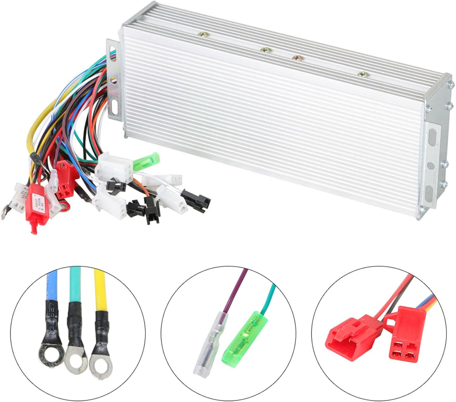
Image 3.3: Various types of connectors and terminals included with the controller, indicating different functions for motor, battery, and accessory connections.
4. Ntọala na nwụnye
Careful wiring is crucial for the correct and safe operation of the motor controller. Refer to the detailed wiring diagram below and ensure each connection is made accurately.

Image 4.1: Comprehensive wiring diagram illustrating the connections for the motor controller. Key connections include:
- Motor Line: Connects to the motor phases (typically three thick wires).
- Positive Electrode / Negative Electrode: Main power input from the battery.
- Mkpọchi: Ignition switch connection.
- Alarm Power Supply / Alarm Wire: For security system integration.
- Study Wire: Used for initial motor learning/pairing.
- Ụlọ Nzukọ: Hall sensor connections from the motor.
- Ụgbọ mmiri: For cruise control functionality.
- High Brake / Low Brake: Connections for brake levers (high or low electrical level).
- tụgharịa: For reverse gear functionality.
- Instruments / LCD Display: Connections for dashboard display or LCD panel.
- Oche: Connects to the throttle grip.
- Three Speed: For multi-speed selection.
Nzọụkwụ nwụnye:
- Ugwu onye njikwa: Securely mount the controller in a location that is protected from direct impact, water, and excessive heat, allowing for adequate airflow around its aluminum casing.
- Connect Motor Wires: Connect the three thick motor phase wires from the controller to the corresponding motor phase wires.
- Connect Hall Sensor Wires: Connect the smaller Hall sensor wires from the controller to the motor's Hall sensor wires.
- Connect Battery Power: Connect the main positive and negative power wires from the controller to your 48-72V battery, ensuring correct polarity.
- Connect Ignition Lock: Connect the ignition lock wire. The controller will only power on when this circuit is closed.
- Connect Throttle: Attach the throttle wire to the throttle grip.
- Connect Brake Levers: Connect the High Brake and/or Low Brake wires to your brake levers.
- Jikọọ Ngwa: Connect any additional accessories such as the LCD display, instruments, alarm system, cruise control, or three-speed switch as per the diagram.
- Perform Study Wire Pairing (if applicable): Some controllers require a 'study wire' connection to automatically identify motor parameters. Follow specific instructions for your motor if this feature is present.
- Nyochaa njikọ: Double-check all connections for tightness and correct placement before applying power.
5. Ntuziaka ọrụ
Once properly installed, the WFLNHB motor controller provides sensitive and efficient control over your brushless DC motor. This controller supports a 2-mode operation, allowing for flexible power delivery.
- Ike Na: Turn the ignition key (if connected) or activate the main power switch. The controller will perform a self-check.
- Njikwa trotul: Gently twist the throttle grip to accelerate. The controller's sensitive response ensures smooth acceleration and deceleration.
- breeki: Engaging the brake levers will cut power to the motor, providing a safe stop. The controller supports both high and low electrical level brake signals.
- 2-Mode Operation: The controller is designed with a 2-mode function, which typically refers to dual-mode control (e.g., Hall sensor mode and sensorless mode). This allows for continued operation even if Hall sensors fail, or provides optimized performance under different conditions. Consult your motor's specifications for optimal mode utilization.
- Speed Selection (if connected): If a three-speed switch is connected, use it to select your desired speed mode (e.g., low, medium, high).
6. Nlekọta
To ensure the longevity and optimal performance of your WFLNHB motor controller, follow these general maintenance guidelines:
- Nyocha oge niile: Periodically check all wiring connections for tightness and signs of wear or corrosion. Ensure no wires are pinched or exposed.
- Ịdị ọcha: Keep the controller free from dust, dirt, and debris. Use a dry, soft cloth to wipe down the exterior. Do not use liquid cleaners directly on the controller.
- Mgbasa ọkụ: Ensure the controller's mounting location allows for adequate airflow to its aluminum casing. Do not obstruct the heat dissipation fins.
- Nchekwa gburugburu: Protect the controller from direct exposure to rain, snow, or extreme humidity.
- Ahụike batrị: Maintain your battery according to its manufacturer's instructions. A healthy battery contributes to stable controller operation.
7. Nchọpụta nsogbu
If you encounter issues with your motor controller, refer to the following common problems and solutions:
- moto anaghị aza:
- Lelee ọkwa chaja batrị.
- Verify all power connections (positive, negative, ignition lock).
- Inspect throttle wiring for damage or loose connections.
- Ensure motor phase and Hall sensor wires are correctly connected.
- Intermittent Power/Operation:
- Check for loose or corroded connections, especially main power and motor wires.
- Inspect for any short circuits or damaged insulation on wires.
- Ensure the controller is not overheating (check mounting and airflow).
- Motor Runs Rough or Makes Unusual Noise:
- Verify Hall sensor connections are correct and undamaged.
- Check motor phase wire connections.
- If the controller has a 'study wire' function, re-perform the motor learning process.
- Brakes Not Functioning Correctly:
- Check brake lever switch wiring to the controller.
- Ensure the brake signal type (high/low electrical level) matches the controller's input.
If problems persist after troubleshooting, contact customer support for further assistance.
8. Nkọwapụta
Technical specifications for the WFLNHB 48-72V 1000W Brushless DC Electric Motor Speed Control Box:

Image 8.1: Dimensions of the WFLNHB motor controller.
| Njirimara | Nkọwapụta |
|---|---|
| Onye nrụpụta | WFLNHB |
| Voltage | 48-72 volts |
| Ike | 1000W |
| Ihe onwunwe | Aluminom |
| Akụkụ (L x W x H) | 7.2 x 3.22 x 1.57 inch (ihe dị ka) |
| Ibu Ibu | 1.41 pound (gram 640) |
| Ụdị breeki | High/Low Electrical Level |
| Akụkụ akụkụ | 60°/120° Automatic Identification |
| Display Type Compatibility | LED ma ọ bụ LCD |
9. Akwụkwọ ikike na nkwado
For warranty information or technical support regarding your WFLNHB 48-72V 1000W Brushless DC Electric Motor Speed Control Box, please refer to the documentation provided with your purchase or contact WFLNHB customer service directly through their official channels. Ensure you have your product model and purchase details available when seeking support.