1. Okwu mmalite
This manual provides comprehensive instructions for the installation, operation, and maintenance of the Chieftec CI-01B-OP mATX Chasis. This chassis is designed for micro-ATX systems, offering a compact yet versatile solution for PC builders. Please read this manual thoroughly before beginning any installation.

This image displays the Chieftec CI-01B-OP mATX Chasis from a front-side angle, highlighting its black finish and honeycomb mesh front panel design.
2. Ihe ngwugwu
Please verify that all items listed below are present in your package before proceeding with installation. If any items are missing or damaged, contact your retailer.
- Chieftec CI-01B-OP mATX Chasis
- Ntọala nke kposara skru
- Nzacha uzuzu
- HDD rails
- Mounting instructions (this manual)
3. Atụmatụ igodo
The Chieftec CI-01B-OP mATX Chasis offers several features designed for ease of use and performance:
- Ihe kpatara ụdị: Compact mATX cube design.
- Ogwe ihu: Honeycomb stamped mesh for optimized airflow.
- Ọdụ ụgbọ mmiri I/O n'ihu: 2x USB 3.0, 1x USB 2.0, Mic-in, Audio-out (AZALIA / HD-Audio).
- Bgbọala Oge: 1x 5.25" external, 2x 3.5" internal, 3x 2.5" internal.
- VGA Card Support: Maximum length of 320mm.
- CPU Cooler Support: Maximum height of 150mm.
- Ihe: Durable 0.6mm thick metal construction.

This image shows a close-up of the top panel of the chassis, detailing the integrated USB 3.0, USB 2.0, microphone, and audio ports.
4. Ntọala na nwụnye
Follow these steps for proper component installation. Ensure the system is powered off and unplugged from the wall outlet before beginning any installation to prevent electric shock or damage to components.
4.1. Preparing the Chasis
Remove the side panels and any necessary covers to access the interior. Refer to the chassis diagram for panel removal instructions.
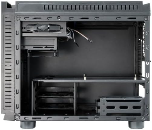
Foto a na-egosi ihe dị n'ime view of the chassis, showing the motherboard tray, drive bays, and general component layout.
4.2. Nwụnye motherboard
- Install the I/O shield into the rear opening of the chassis.
- Align your micro-ATX motherboard with the pre-installed standoffs inside the chassis.
- Chekwaa motherboard site na iji kposara enyere. Akwụsịla elu.
4.3. Nrụnye Ike Ike (PSU).
- Mount the PSU in its designated area, typically at the rear bottom of the chassis.
- Chekwaa PSU site na skru n'azụ chassis.
4.4. Mbanye nwụnye
- 3.5 "HDDs: Attach the provided HDD rails to your 3.5" hard drives and slide them into the internal 3.5" drive bays until they click into place.
- SSD/HDD 2.5": Secure 2.5" solid-state drives or hard drives into the dedicated 2.5" bays using screws.
- 5.25" ODD: Install 5.25" optical drives into the external bay from the front and secure them with screws or tool-less mechanisms if available.
4.5. Graphics Card (VGA) Installation
- Remove the necessary expansion slot covers at the rear of the chassis.
- Insert the graphics card into the appropriate PCIe slot on the motherboard.
- Secure the graphics card with a screw or latch. Ensure the card's length does not exceed 320mm.
4.6. Ntinye ihe mkpuchi CPU
Install your CPU cooler according to its manufacturer's instructions. Ensure the cooler's height does not exceed 150mm to allow the side panel to close properly.
4.7. Njikwa USB
Route power and data cables neatly behind the motherboard tray or through designated cutouts. This improves airflow and maintains a clean interior aesthetic.

This image shows the chassis with its top and side panels opened, revealing the internal structure and providing a clear view of the space available for component installation and cable routing.
4.8. Ijikọ eriri Panel dị n'ihu
Connect the front panel USB 3.0, USB 2.0, audio, power switch, reset switch, and LED cables to the corresponding headers on your motherboard. Refer to your motherboard manual for specific header locations and pin assignments.
5. Ọrụ
Once all components are securely installed and connected, carefully close and secure the chassis panels. Connect the power cable to the PSU and an electrical outlet. Press the power button on the front panel to start your system.
6. Nlekọta
Regular maintenance helps ensure optimal performance and longevity of your chassis and its components.
- Ihe nzacha uzuzu: Periodically clean the dust filters (e.g., front mesh, bottom PSU filter) to maintain good airflow and prevent dust buildup inside the system. Dust can impede cooling efficiency.
- Ime nhicha: Use compressed air to remove dust from internal components and fans. Ensure the system is powered off and unplugged before cleaning. Avoid using liquid cleaners inside the chassis.
- Nchacha mpụta: Wipe the exterior surfaces with a soft, slightly damp akwa . Zere iji kemịkalụ siri ike ma ọ bụ ihe na-emebi emebi nwere ike imebi njedebe.
7. Nchọpụta nsogbu
This section addresses common issues you might encounter during or after installation.
- System does not power on:
Check all power connections, including the PSU to the wall outlet, the 24-pin ATX power cable and 8-pin CPU power cable from the PSU to the motherboard, and the front panel power switch cable to the motherboard header. Ensure the PSU switch is in the 'ON' position.
- Enweghị ngosipụta mmepụta:
Ensure the graphics card is properly seated in its PCIe slot and connected to auxiliary power (if required). Verify the monitor cable is securely connected to the graphics card and the monitor is powered on and set to the correct input.
- Ndị Fans anaghị agbagharị agbagharị:
Check all fan connections to the motherboard or any fan controller. Ensure power cables are properly connected to the fans.
- Front USB ports not working:
Verify that the front panel USB cables (USB 3.0 and USB 2.0) are correctly connected to the corresponding USB headers on your motherboard.
8. Nka na ụzụ nkọwa
| Njirimara | Nkọwapụta |
|---|---|
| Aha Nlereanya | CI-01B-OP |
| Ụdị Ihe | mATX Cube |
| Akụkụ (LxWxH) | 15.75 x 18.11 x 12.99 sentimita (400 x 460 x 330 mm) |
| Ibu Ibu | 11.22 pound (5.1 n'arọ) |
| Ihe onwunwe | Metal (0.6mm thick) |
| Agba | Nwa |
| External Drive Bays | 1x 5.25" |
| Ọnụ ụzọ mbanye nke ime | 2x 3.5", 3x 2.5" |
| N'ihu I / O Ports | 2x USB 3.0, 1x USB 2.0, Mic-in, Audio-out |
| Ndakọrịta Motherboard | Micro ATX |
| Ogologo Kaadị VGA Max VGA | 320mm |
| Max CPU cooler elu | 150mm |
| Ịkwanye ọkụ ọkụ | Ugwu azụ |
| Usoro jụrụ oyi | Ikuku |
9. Akwụkwọ ikike na nkwado
For detailed warranty information, technical support, or service inquiries, please refer to the official Chieftec webma ọ bụ kpọtụrụ onye na-ere ahịa mpaghara gị ebe azụrụ ngwaahịa ahụ. Biko debe ihe akaebe nke ịzụrụ ihe gị maka akwụkwọ ikike ọ bụla.
Official Chieftec Websaịtị: https://www.chieftec.eu